Basic VPRN Configuration on Nokia Service Routers. VPRN (Virtual Private Routed Network) this is a Layer 3 VPN technology and generally used Nokia Routers in Service provider domain. This article will guide you through the easiest approach to VPRN, how to configure and test the VPRN operation.
Mục lục
Prepare
You need to prepare the following basic information by yourself, otherwise you can download the initialization configuration at the end of the article.
- Router Name (R1,R2…R6)
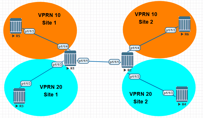
- Port Number (no shutdown, default mode network). Like bellow topology:
- All router interfaces are named toRX, where X is the router number..
- The system address is 10.10.10.X/32, with X as the router number.
- The IP address for all interfaces is numbered 10.X.Y.R/27, where
- X is the lower router,
- Y is the higher router, and
- R is the local router.
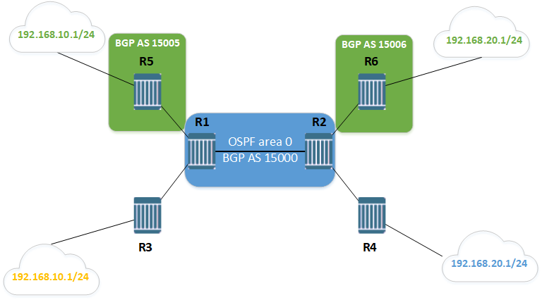
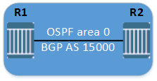
- Configure OSPF area 0 in core. Remember to network system interface to OSPF.
Provider Core Configuration
In this section, the core will be configured to allow the sites within a VPRN service to communicate with each other.
On routers R1 and R2, enable LDP on the core-facing network interfaces.
#R1#
/configure router ldp interface-parameters interface "toR2"

#R2#
/configure router ldp interface-parameters interface "toR1"
Configure an MP-BGP session between routers R1 and R2. Use AS 15000 and enable support for the exchange of VPN-IPv4 prefixes between them.
#R1#
/configure router autonomous-system 15000
/configure router bgp
family vpn-ipv4
group "MP-BGP"
peer-as 15000
local-address 10.10.10.1
neighbor 10.10.10.2

#R2#
/configure router autonomous-system 15000
/configure router bgp
family vpn-ipv4
group "MP-BGP"
peer-as 15000
local-address 10.10.10.2
neighbor 10.10.10.1
Verify the LDP session is operational.
A:R1# show router ldp session

==============================================================================
LDP IPv4 Sessions
==============================================================================
Peer LDP Id         Adj Type  State         Msg Sent  Msg Recv  Up Time
------------------------------------------------------------------------------
10.10.10.2:0        Link      Established   29069     28810     0d 21:33:00
------------------------------------------------------------------------------
No. of IPv4 Sessions: 1
==============================================================================
Verify the MP-BGP session has been established.
A:R1# show router bgp neighbor
...
-------------------------------------------------------------------------------
Peer : 10.10.10.2
Description : (Not Specified)
Group : MP-BGP
-------------------------------------------------------------------------------
Peer AS : 15000 Peer Port : 50694
Peer Address : 10.10.10.2
Local AS : 15000 Local Port : 179
Local Address : 10.10.10.1
Peer Type : Internal Dynamic Peer : No
State : Established Last State : Established
Last Event : recvOpen
Last Error : Cease (Connection Collision Resolution)
Local Family : VPN-IPv4
Remote Family : VPN-IPv4
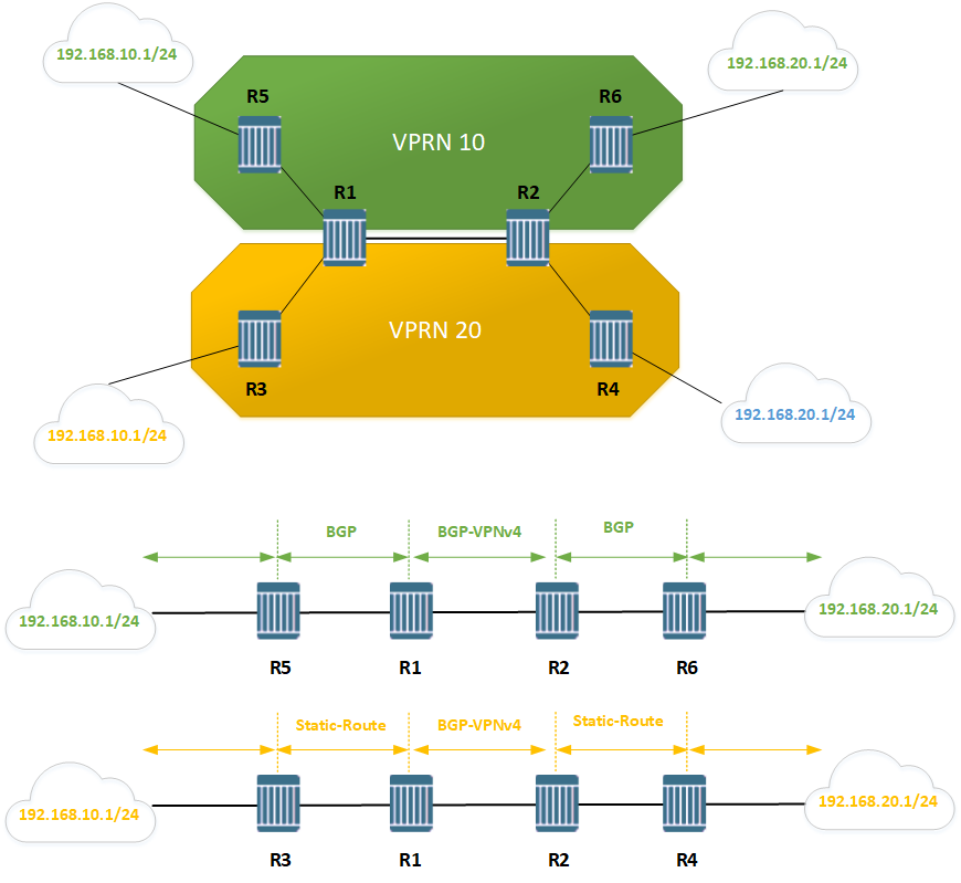
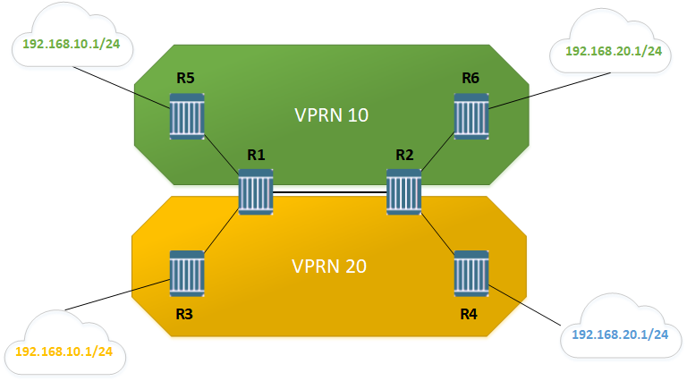
...VPRN 10 Configuration with BGP
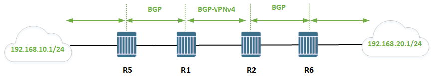
In this section, VPRN ID 10 will be created to connect the customer CE routers R5 and R6. One of the sites will use BGP as the PE-CE routing protocol, while the other site will use static routing.
To simulate locally-connected networks, create the following loopback interfaces:
On router R5, create a loopback interface with address 192.168.10.1/24
/configure router interface "vprn10_r5"
address 192.168.10.1/24
loopback
On router R6, create a loopback interface with address 192.168.20.1/24
/configure router interface "vprn10_r6"
address 192.168.20.1/24
loopback
On routers R1 and R2, create a VPRN with service ID = 10
- Switch the downlink port to the client as the access port
- Define the RD as being :10
- Define the route target as being of Type 0 and value target::10
- Create the interface facing routers R5 and R6.
- Force the VPRN to use LDP-based transport tunnels.
- Turn up the service and verify it is operational on both routers R1 and R2.
#R1#
/configure port 1/1/3 ethernet mode access
/configure port 1/1/3 no shutdown

/configure service vprn 10 customer 1 create
description "VPRN 10"
router-id 10.10.10.1
autonomous-system 15000
route-distinguisher 15000:10
auto-bind-tunnel resolution-filter ldp
auto-bind-tunnel resolution filter
vrf-target target:15000:10
interface "toCE-R5" create
address 10.1.5.1/27
sap 1/1/4 create
exit
exit
no shutdown
exit

#R2#
/configure port 1/1/3 ethernet mode access
/configure port 1/1/3 no shutdown

/configure service vprn 10 customer 1 create
description "VPRN 10"
router-id 10.10.10.2
autonomous-system 15000
route-distinguisher 15000:10
auto-bind-tunnel resolution-filter ldp
auto-bind-tunnel resolution filter
vrf-target target:15000:10
interface "toCE-R6" create
address 10.2.6.2/27
sap 1/1/4 create
exit
exit
no shutdown
exit
A:R1# show service id 10 base
...
Service Id : 10 Vpn Id : 0
Service Type : VPRN
Description : VPRN 10
...
Admin State : Up Oper State : Up
Router Oper State : Up
Route Dist. : 15000:10 VPRN Type : regular
Oper Route Dist : 15000:10
Oper RD Type : configured
AS Number : 15000 Router Id : 10.10.10.1
...
Auto Bind Tunnel
...
Resolution : filter
Filter Protocol : ldp
...
Vrf Target : target:15000:10
...
-------------------------------------------------------------------------------
Identifier Type AdmMTU OprMTU Adm Opr
-------------------------------------------------------------------------------
sap:1/1/4 null 1514 1514 Up Up
===============================================================================
Configure BGP as the routing protocol between routers R1 and R5.
1/ On router R5, configure an autonomous system of 15005. Create a policy to control the advertisement of the locally-connected routes into BGP.
/configure router autonomous-system 15005

/configure router policy-options
begin
policy-statement "direct-bgp"
    entry 10
        from
            protocol direct
        exit
        to
            protocol bgp
        exit
        action accept
        exit
    exit
exit
commit
On router R5, configure a BGP peer to router R1 and assign the new export policy.
/configure router bgp
group "VPRN 10"
peer-as 15000
neighbor 10.1.5.1
export "direct-bgp"
On router R1, create a policy to exchange VPRN routes from MP-BGP to BGP.
/configure router policy-options
begin
policy-statement "mpbgp-bgp"
    entry 10
        from
            protocol bgp-vpn
        exit
        to
            protocol bgp
        exit
        action accept
        exit
    exit
exit
commit
On router R1, under the service context, configure router R5 as a BGP peer and apply the new export policy.
/configure service vprn 10
bgp group toCE-R5
export mpbgp-bgp
neighbor 10.1.5.5
peer-as 15005
Configure BGP as the routing protocol between routers R2 and R6.
Similar configuration between R1 and R5
#R6#
/configure router autonomous-system 15006

/configure router policy-options
begin
policy-statement "direct-bgp"
    entry 10
        from
            protocol direct
        exit
        to
            protocol bgp
        exit
        action accept
        exit
    exit
exit
commit

/configure router bgp group "VPRN 10"
peer-as 15000
neighbor 10.2.6.2
export "direct-bgp"

#R2#
/configure router policy-options
begin
policy-statement "mpbgp-bgp"
    entry 10
        from
            protocol bgp-vpn
        exit
        to
            protocol bgp
        exit
        action accept
        exit
    exit
exit
commit

/configure service vprn 10
bgp group toCE-R6
export mpbgp-bgp
neighbor 10.2.6.6
peer-as 15006
Verification
Verify the BGP session between routers R1 – R5 and R2 – R6 is established.
A:R1# show router 10 bgp summary
===============================================================================
 BGP Router ID:10.10.10.1       AS:15000       Local AS:15000
===============================================================================
BGP Admin State         : Up          BGP Oper State              : Up
Total Peer Groups       : 1           Total Peers                 : 1
Current Internal Groups : 1           Max Internal Groups         : 1
Total BGP Paths         : 10          Total Path Memory           : 3656
...
===============================================================================
Neighbor
Description
                   AS PktRcvd InQ  Up/Down   State|Rcv/Act/Sent (Addr Family)
                      PktSent OutQ
-------------------------------------------------------------------------------
10.1.5.5
               15005     2744    0 22h47m22s 6/2/5 (IPv4)
                         2745    0
-------------------------------------------------------------------------------
A:R2# show router 10 bgp summary
===============================================================================
 BGP Router ID:10.10.10.2       AS:15000       Local AS:15000
===============================================================================
BGP Admin State         : Up          BGP Oper State              : Up
Total Peer Groups       : 1           Total Peers                 : 1
Current Internal Groups : 1           Max Internal Groups         : 1
Total BGP Paths         : 10          Total Path Memory           : 3656
...
===============================================================================
Neighbor
Description
                   AS PktRcvd InQ  Up/Down   State|Rcv/Act/Sent (Addr Family)
                      PktSent OutQ
-------------------------------------------------------------------------------
10.2.6.6
               15006     2611    0 21h42m30s 6/2/5 (IPv4)
                         2610    0
-------------------------------------------------------------------------------
Check route-table in R5 and R6
A:R5# show router route-table
...
===============================================================================
Dest Prefix[Flags]                            Type    Proto     Age        Pref
      Next Hop[Interface Name]                                    Metric
-------------------------------------------------------------------------------
10.1.5.0/27                                   Local   Local     23h11m12s  0
       toR1                                                         0
10.2.6.0/27                                   Remote  BGP       23h09m37s  170
       10.1.5.1                                                     0
10.10.10.5/32                                 Local   Local     23h12m07s  0
       system                                                       0
10.10.10.6/32                                 Remote  BGP       21h58m27s  170
       10.1.5.1                                                     0
192.168.10.0/24                               Local   Local     23h12m07s  0
       vprn10_r5                                                    0
192.168.20.0/24                               Remote  BGP       21h58m27s  170
       10.1.5.1                                                     0
...
A:R6# show router route-table
...
===============================================================================
Dest Prefix[Flags] Type Proto Age Pref
Next Hop[Interface Name] Metric
-------------------------------------------------------------------------------
10.1.5.0/27 Remote BGP 22h00m37s 170
10.2.6.2 0
10.2.6.0/27 Local Local 23h12m28s 0
toR2 0
10.10.10.5/32 Remote BGP 22h00m37s 170
10.2.6.2 0
10.10.10.6/32 Local Local 23h13m30s 0
system 0
192.168.10.0/24 Remote BGP 22h00m37s 170
10.2.6.2 0
192.168.20.0/24 Local Local 23h13m30s 0
vprn10_r6 0
...From router R5, ping 192.168.20.1 and from router R6 ping 192.168.10.1
A:R5# ping 192.168.20.1  count 1
PING 192.168.20.1 56 data bytes
64 bytes from 192.168.20.1: icmp_seq=1 ttl=62 time=33.9ms.

---- 192.168.20.1 PING Statistics ----
1 packet transmitted, 1 packet received, 0.00% packet loss
round-trip min = 33.9ms, avg = 33.9ms, max = 33.9ms, stddev = 0.000ms
A:R6# ping 192.168.10.1  count  1
PING 192.168.10.1 56 data bytes
64 bytes from 192.168.10.1: icmp_seq=1 ttl=62 time=35.2ms.

---- 192.168.10.1 PING Statistics ----
1 packet transmitted, 1 packet received, 0.00% packet loss
round-trip min = 35.2ms, avg = 35.2ms, max = 35.2ms, stddev = 0.000ms
Perform a vprn trace between routers R1 and R2
A:R1# oam vprn-trace 10 source 10.1.5.1 destination 10.2.6.2

TTL Seq Rcvd-on                                   Reply-Path RTT
----------------------------------------------------------------------------
[Send request TTL: 1, Seq. 1.]
1   1   cpm                                       In-Band    2.42ms
Node-Id 10.10.10.2
  Requestor 10.10.10.1
    Route: 10.2.6.0/27
    Vpn Label: 524286 Metrics 2 Pref 170 Owner bgpVpn
    Next Hops: [1] ldp tunnel
    Route Targets: [1]: target:15000:10
  Responder 10.10.10.2
    Route: 10.2.6.2/32
    Vpn Label: 0 Metrics 0 Pref 0 Owner local
    Next Hops: [1] ifIdx 3 nextHopIp none

----------------------------------------------------------------------------
VPRN 20 Configuration with static route
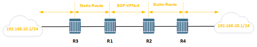
In this section, a second VPRN (ID=20) using the same PE routers will be created. Customer sites belonging to different VPRNs will be able to use the same private IP address space. The original VPRN will not be modified.
Create the following loopback interfaces
To simulate locally-connected networks, create the following loopback interfaces making sure to use the same addresses of the loopback interfaces in the previous section.
On router R3, create a loopback interface with address 192.168.10.1/24
/configure router interface vprn20_r3
address 192.168.10.1/24
loopback
On router R4, create a loopback interface with address 192.168.20.1/24
/configure router interface vprn20_r4
address 192.168.20.1/24
loopback
The loopback interface addresses on routers R3 and R4 are the same as those configured on routers R5 and R6 respectively. This illustrates the point that IP addresses can be re-used within different VPRNs.
On routers R1 and R2, create a VPRN with service ID = 20
- Switch the downlink port to the client as the access port
- Define the RD as being :20
- Define the route target as being of Type 0 and value target::20
- Create the interface facing routers R5 and R6.
- Force the VPRN to use LDP-based transport tunnels.
- Turn up the service and verify it is operational on both routers R1 and R2.
Perform the same configuration of the VPNN service as in the previous section.
#R1#
/configure port 1/1/4 ethernet mode access
/configure port 1/1/4 no shutdown

/configure service vprn 20 customer 1 create
description "VPRN 20"
router-id 10.10.10.1
autonomous-system 15000
interface "toCE-R3" create
    address 10.1.3.1/27
    sap 1/1/3 create
    exit
exit
bgp-ipvpn
    mpls
        auto-bind-tunnel
            resolution-filter
                ldp
            exit
            resolution filter
        exit
        route-distinguisher 15000:20
        vrf-target target:15000:20
        no shutdown
    exit
exit
no shutdown

#R2#
/configure port 1/1/4 ethernet mode access
/configure port 1/1/4 no shutdown

/configure service vprn 20 customer 1 create
description "VPRN 20"
router-id 10.10.10.2
autonomous-system 15000
interface "toCE-R4" create
    address 10.2.4.2/27
    sap 1/1/3 create
    exit
exit
bgp-ipvpn
    mpls
        auto-bind-tunnel
            resolution-filter
                ldp
            exit
            resolution filter
        exit
        route-distinguisher 15000:20
        vrf-target target:15000:20
        no shutdown
    exit
exit
no shutdown
Use static routing to configure the forwarding of VPRN routes between routers R1 and R3 and routers R2 and R4.
#R1#
/configure service vprn 20 static-route-entry 192.168.10.0/24 next-hop 10.1.3.3 no shutdown

#R3#
/configure router static-route-entry 0.0.0.0/0 next-hop 10.1.3.1 no shutdown

#R2#
/configure service vprn 20 static-route-entry 192.168.20.0/24 next-hop 10.2.4.4 no shutdown

#R4#
/configure router static-route-entry 0.0.0.0/0 next-hop 10.2.4.2 no shutdown
Verification
Verify the static route configuration between routers R1 and R3 and routers R2 and R4.
A:R3# show router static-route
===============================================================================
Static Route Table (Router: Base)  Family: IPv4
===============================================================================
Prefix                                        Tag         Met    Pref Type Act
   Next Hop                                    Interface
-------------------------------------------------------------------------------
0.0.0.0/0                                     0           1      5    NH   Y
   10.1.3.1                                    toR1
-------------------------------------------------------------------------------
No. of Static Routes: 1
===============================================================================
A:R1# show router 20 static-route
===============================================================================
Static Route Table (Service: 20) Family: IPv4
===============================================================================
Prefix Tag Met Pref Type Act
Next Hop Interface
-------------------------------------------------------------------------------
192.168.10.0/24 0 1 5 NH Y
10.1.3.3 toCE-R3
-------------------------------------------------------------------------------
No. of Static Routes: 1
===============================================================================A:R4# show router static-route
===============================================================================
Static Route Table (Router: Base) Family: IPv4
===============================================================================
Prefix Tag Met Pref Type Act
Next Hop Interface
-------------------------------------------------------------------------------
0.0.0.0/0 0 1 5 NH Y
10.2.4.2 toR2
-------------------------------------------------------------------------------
No. of Static Routes: 1
===============================================================================A:R2# show router 20 static-route
===============================================================================
Static Route Table (Service: 20) Family: IPv4
===============================================================================
Prefix Tag Met Pref Type Act
Next Hop Interface
-------------------------------------------------------------------------------
192.168.20.0/24 0 1 5 NH Y
10.2.4.4 toCE-R4
-------------------------------------------------------------------------------
No. of Static Routes: 1
===============================================================================On router R3, perform a traceroute to 192.168.20.1, using 192.168.10.1 as the source interface. The traceroute goes through interface 10.2.4.2, which is facing router R4.
A:R3# traceroute 192.168.20.1 source 192.168.10.1
traceroute to 192.168.20.1 from 192.168.10.1, 30 hops max, 40 byte packets
  1  10.1.3.1 (10.1.3.1)    3.83 ms  1.21 ms  1.08 ms
  2  10.2.4.2 (10.2.4.2)    2.57 ms  32.5 ms  36.5 ms
  3  192.168.20.1 (192.168.20.1)    16.2 ms  6.55 ms  16.3 ms
That’s all of Basic VPRN Configuration on Nokia Service Routers. If there are any questions or discussions, do not hesitate to comment down below the article. Good luck!
You can download the resources for the VPRN lab (init config, unl file) below:
Just a suggestion to include show commands below.
*A:R1# show router bgp neighbor 22.22.22.22 received-routes vpn-ipv4
===============================================================================
BGP Router ID:11.11.11.11 AS:65000 Local AS:65000
===============================================================================
Legend –
Status codes : u – used, s – suppressed, h – history, d – decayed, * – valid
l – leaked, x – stale, > – best, b – backup, p – purge
Origin codes : i – IGP, e – EGP, ? – incomplete
===============================================================================
BGP VPN-IPv4 Routes
===============================================================================
Flag Network LocalPref MED
Nexthop (Router) Path-Id IGP Cost
As-Path Label
——————————————————————————-
u*>i 22.22.22.22:300:6.6.6.0/24 100 0
22.22.22.22 None 1
600 524286
u*>i 22.22.22.22:300:66.66.66.0/30 100 None
22.22.22.22 None 1
No As-Path 524286
u*>i 22.22.22.22:300:66.66.66.66/32 100 0
22.22.22.22 None 1
600 524286
——————————————————————————-
Routes : 3
===============================================================================
*A:R1# show router bgp neighbor 22.22.22.22 received-routes
===============================================================================
BGP Router ID:11.11.11.11 AS:65000 Local AS:65000
===============================================================================
Legend –
Status codes : u – used, s – suppressed, h – history, d – decayed, * – valid
l – leaked, x – stale, > – best, b – backup, p – purge
Origin codes : i – IGP, e – EGP, ? – incomplete
===============================================================================
BGP IPv4 Routes
===============================================================================
Flag Network LocalPref MED
Nexthop (Router) Path-Id IGP Cost
As-Path Label
——————————————————————————-
No Matching Entries Found.
===============================================================================
*A:R1#
*A:R1# show router bgp routes vpn-ipv4
===============================================================================
BGP Router ID:11.11.11.11 AS:65000 Local AS:65000
===============================================================================
Legend –
Status codes : u – used, s – suppressed, h – history, d – decayed, * – valid
l – leaked, x – stale, > – best, b – backup, p – purge
Origin codes : i – IGP, e – EGP, ? – incomplete
===============================================================================
BGP VPN-IPv4 Routes
===============================================================================
Flag Network LocalPref MED
Nexthop (Router) Path-Id IGP Cost
As-Path Label
——————————————————————————-
u*>i 22.22.22.22:300:6.6.6.0/24 100 0
22.22.22.22 None 1
600 524286
u*>i 22.22.22.22:300:66.66.66.0/30 100 None
22.22.22.22 None 1
No As-Path 524286
u*>i 22.22.22.22:300:66.66.66.66/32 100 0
22.22.22.22 None 1
600 524286
u*>i 33.33.33.33:300:7.7.7.0/24 100 0
33.33.33.33 None 1
700 524286
u*>i 33.33.33.33:300:77.77.77.0/30 100 None
33.33.33.33 None 1
No As-Path 524286
u*>i 33.33.33.33:300:77.77.77.77/32 100 0
33.33.33.33 None 1
700 524286
u*>i 44.44.44.44:300:8.8.8.0/24 100 0
44.44.44.44 None 1
800 524286
u*>i 44.44.44.44:300:88.88.88.0/30 100 None
44.44.44.44 None 1
No As-Path 524286
u*>i 44.44.44.44:300:88.88.88.88/32 100 0
44.44.44.44 None 1
800 524286
——————————————————————————-
Routes : 9
===============================================================================
*A:R1#
*A:R1# show router bgp summary family vpn-ipv4
===============================================================================
BGP Router ID:11.11.11.11 AS:65000 Local AS:65000
===============================================================================
BGP Admin State : Up BGP Oper State : Up
Total Peer Groups : 1 Total Peers : 3
Total VPN Peer Groups : 1 Total VPN Peers : 1
Current Internal Groups : 1 Max Internal Groups : 1
Total BGP Paths : 50 Total Path Memory : 17704
Total IPv4 Remote Rts : 0 Total IPv4 Rem. Active Rts : 0
Total IPv6 Remote Rts : 0 Total IPv6 Rem. Active Rts : 0
Total IPv4 Backup Rts : 0 Total IPv6 Backup Rts : 0
Total LblIpv4 Rem Rts : 0 Total LblIpv4 Rem. Act Rts : 0
Total LblIpv6 Rem Rts : 0 Total LblIpv6 Rem. Act Rts : 0
Total LblIpv4 Bkp Rts : 0 Total LblIpv6 Bkp Rts : 0
Total Supressed Rts : 0 Total Hist. Rts : 0
Total Decay Rts : 0
Total VPN-IPv4 Rem. Rts : 9 Total VPN-IPv4 Rem. Act. Rts: 9
Total VPN-IPv6 Rem. Rts : 0 Total VPN-IPv6 Rem. Act. Rts: 0
Total VPN-IPv4 Bkup Rts : 0 Total VPN-IPv6 Bkup Rts : 0
Total VPN Local Rts : 4 Total VPN Supp. Rts : 0
Total VPN Hist. Rts : 0 Total VPN Decay Rts : 0
Total MVPN-IPv4 Rem Rts : 0 Total MVPN-IPv4 Rem Act Rts : 0
Total MVPN-IPv6 Rem Rts : 0 Total MVPN-IPv6 Rem Act Rts : 0
Total MDT-SAFI Rem Rts : 0 Total MDT-SAFI Rem Act Rts : 0
Total McIPv4 Remote Rts : 0 Total McIPv4 Rem. Active Rts: 0
Total McIPv6 Remote Rts : 0 Total McIPv6 Rem. Active Rts: 0
Total McVpnIPv4 Rem Rts : 0 Total McVpnIPv4 Rem Act Rts : 0
Total McVpnIPv6 Rem Rts : 0 Total McVpnIPv6 Rem Act Rts : 0
Total EVPN Rem Rts : 0 Total EVPN Rem Act Rts : 0
Total L2-VPN Rem. Rts : 0 Total L2VPN Rem. Act. Rts : 0
Total MSPW Rem Rts : 0 Total MSPW Rem Act Rts : 0
Total RouteTgt Rem Rts : 0 Total RouteTgt Rem Act Rts : 0
Total FlowIpv4 Rem Rts : 0 Total FlowIpv4 Rem Act Rts : 0
Total FlowIpv6 Rem Rts : 0 Total FlowIpv6 Rem Act Rts : 0
Total Link State Rem Rts: 0 Total Link State Rem Act Rts: 0
Total SrPlcyIpv4 Rem Rts: 0 Total SrPlcyIpv4 Rem Act Rts: 0
Total SrPlcyIpv6 Rem Rts: 0 Total SrPlcyIpv6 Rem Act Rts: 0
===============================================================================
BGP VPN-IPv4 Summary
===============================================================================
Legend : D – Dynamic Neighbor
===============================================================================
Neighbor
AS PktRcvd PktSent InQ OutQ Up/Down State|Recv/Actv/Sent
——————————————————————————-
22.22.22.22
65000 681 681 0 0 05h36m39s 3/3/3
33.33.33.33
65000 678 680 0 0 05h36m05s 3/3/3
44.44.44.44
65000 679 681 0 0 05h36m49s 3/3/3
——————————————————————————-
*A:R1#