Nokia Router
Basic BGP configuration in Nokia 7750 SR/7705 SAR (Part-1/2)

Th3
The Basic BGP configuration in Nokia 7750 SR/7705 SAR lab scenario aims to equip learners with a comprehensive understanding of various key aspects of Border Gateway Protocol (BGP). Through this lab scenario, participants will be able to gain fundamental knowledge on address management and traffic flows, as well as configure basic iBGP and eBGP neighbors. Additionally, participants will learn about export policies set at both IP edge and borders of the network, and how to manage BGP attributes, including next-hop, local preferences, and AS-path. The lab scenario will also cover the fundamentals of route aggregation and managing the atomic aggregate BGP attribute, further enhancing participants’ understanding of BGP. Overall, the lab scenario is designed to provide learners with hands-on experience in configuring and managing BGP in a real environment setting.
Mục lục
Basic Lab Information
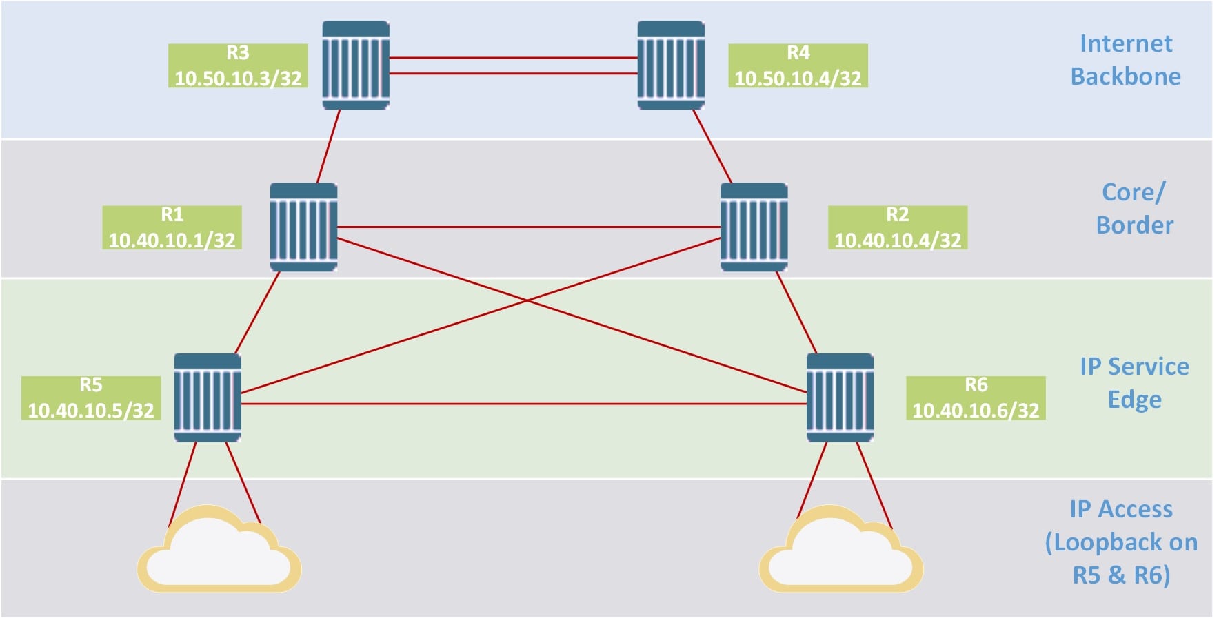
The model includes 6 devices, 2 devices of Internet Backbone, 2 devices of Core/Border class and 2 devices of IP Service Edge class. The system name, ip system and as number information are assigned as shown in the table below:
| Router Name | System IP (/32) | AS Number |
| R1 | 10.40.10.1 | 65540 |
| R2 | 10.40.10.2 | 65540 |
| R3 | 10.40.10.3 | 65550 |
| R4 | 10.40.10.4 | 65550 |
| R5 | 10.40.10.5 | 65540 |
| R6 | 10.40.10.6 | 65540 |
You download the lab file and initialization configuration at the link at the end of the article.
IGP Discovery and Preparing to Deploy BGP
The objective of this section is to verify IGP operations and to lay out the high-level policies that will be used in the next exercise (iBGP). The following operations will be covered:
- Base IS-IS IGP network verification to understand the core, border, and IP edge terminology better.
- IGP traffic analysis. Adjusting IGP metrics to prefer to route over core links vs. over IP edge links.
- Address plan. Creating prefix lists
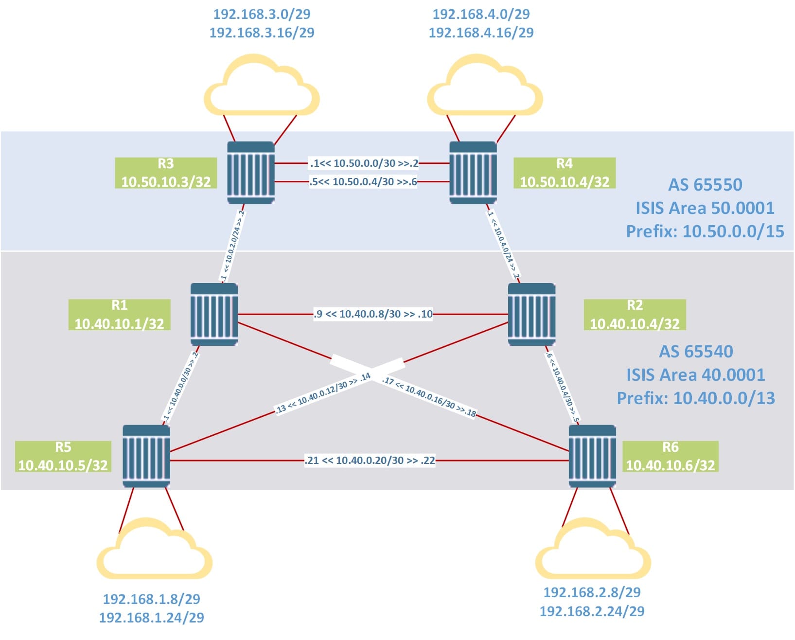
You can configure the IP, ISIS… yourself based on the parameters above the image above or you can download the sample configuration at the download button at the end of the article. After the configuration is complete, make sure all the routers have reached each other.
Let check in R1, R2, R5 and R6:
#R1#
show router route-table 10.40.10.0/24 longer
...
===============================================================================
Dest Prefix[Flags]                            Type    Proto     Age        Pref
      Next Hop[Interface Name]                                    Metric
-------------------------------------------------------------------------------
10.40.10.1/32                                 Local   Local     01d23h37m  0
       system                                                       0
10.40.10.2/32                                 Remote  ISIS      01d03h36m  15
       10.40.0.10                                                   10
10.40.10.5/32                                 Remote  ISIS      01d03h42m  15
       10.40.0.1                                                    100
10.40.10.6/32                                 Remote  ISIS      23h02m18s  15
       10.40.0.14                                                   100
-------------------------------------------------------------------------------
No. of Routes: 4
...
From router R1, shutdown link to R6. From router R2, shutdown link to R5.
#R2#
configure router interface "toR5" shutdown

#R5#
show router route-table  10.40.10.2
...
===============================================================================
Dest Prefix[Flags]                            Type    Proto     Age        Pref
      Next Hop[Interface Name]                                    Metric
-------------------------------------------------------------------------------
10.40.10.2/32                                 Remote  ISIS      00h00m22s  15
       10.40.0.2                                                    200
10.40.10.2/32                                 Remote  ISIS      00h00m22s  15
       10.40.0.22                                                   200
-------------------------------------------------------------------------------
No. of Routes: 2
...
Now, router R6 now has two paths to router R1’s system loopback, and router R5 now has two paths to router R2’s system loopback. We should force traffic from Client side to go to Core/Border go directly from R5 to R1 or R6 to R2. Traffic must not bypass the R5-R6 link. The simplest way is to reduce the cost on the link R1-R2.
#R1#
/configure router isis interface "toR2" level 1 metric 10
/configure router isis interface "toR2" level 2 metric 10

#R2#
/configure router isis interface "toR1" level 1 metric 10
/configure router isis interface "toR1" level 2 metric 10

#R5#
show router route-table  10.40.10.2
...
===============================================================================
Dest Prefix[Flags]                            Type    Proto     Age        Pref
      Next Hop[Interface Name]                                    Metric
-------------------------------------------------------------------------------
10.40.10.2/32                                 Remote  ISIS      00h01m12s  15
       10.40.0.2                                                    110
-------------------------------------------------------------------------------
No. of Routes: 1
...
Prepare prefix-list according to the following requirements:
On both IP Edge routers R5 and R6 create two prefix-lists, “Client-CIDR” and “Client-External”:
- Client-CIDR: Assuming that 10.40.0.0/16 is reserved for internal IGP routing, the first list should define all possible CIDR client address space for the prefix 10.40.0.0/13.
- Client-External: Define a second list that defines all of the “external” client space that should be used by AS 65540 to offer transit service to its clients.
R3 and R4 (Internet Backbone) donot have any special requirements.
#R5 and R6#
/configure router policy-options
begin
prefix-list "Client-CIDR"
prefix 10.41.0.0/16 longer
prefix 10.42.0.0/15 longer
prefix 10.44.0.0/14 longer
exit
prefix-list "Client-External"
prefix 192.168.1.8/29 exact
prefix 192.168.1.24/29 exact
prefix 192.168.2.8/29 exact
prefix 192.168.2.24/29 exact
exit
commit
exit all

#R3 and R4#
/configure router policy-options
begin
prefix-list "External-Networks"
prefix 192.168.3.0/29 exact
prefix 192.168.3.16/29 exact
prefix 192.168.4.0/29 exact
prefix 192.168.4.16/29 exact
exit
commit
exit all
Build the IBGP Mesh
Build the two iBGP meshes in AS 65540 and AS 65550
#R1#
/configure router bgp
group "IBGP"
type internal
peer-as 65540
neighbor 10.40.10.2
exit
neighbor 10.40.10.5
exit
neighbor 10.40.10.6
exit all

#R2#
/configure router bgp
group "IBGP"
type internal
peer-as 65540
neighbor 10.40.10.1
exit
neighbor 10.40.10.5
exit
neighbor 10.40.10.6
exit all

#R5#
/configure router bgp
group "IBGP"
type internal
peer-as 65540
neighbor 10.40.10.1
exit
neighbor 10.40.10.2
exit
neighbor 10.40.10.6
exit all

#R6#
/configure router bgp
group "IBGP"
type internal
peer-as 65540
neighbor 10.40.10.1
exit
neighbor 10.40.10.2
exit
neighbor 10.40.10.5
exit all

#R3#
/configure router bgp
group "IBGP"
type internal
peer-as 65550
neighbor 10.50.10.4
exit all

#R4#
/configure router bgp
group "IBGP"
type internal
peer-as 65550
neighbor 10.50.10.3
exit all
Check the router bgp route and bgp summary. There are no routes in the core as nothing has been exported into BGP yet and there are no established eBGP peers.
A:R1# show router bgp summary all
...
===============================================================================
Neighbor
Description
ServiceId          AS PktRcvd InQ  Up/Down   State|Rcv/Act/Sent (Addr Family)
                      PktSent OutQ
-------------------------------------------------------------------------------
10.40.10.2
Def. Instance  65540     3051    0 01d01h23m 0/0/0 (IPv4)
                         3051    0
10.40.10.5
Def. Instance  65540     3057    0 01d01h23m 0/0/0 (IPv4)
                         3051    0
10.40.10.6
Def. Instance  65540     3060    0 01d00h50m 0/0/0 (IPv4)
                         2991    0
-------------------------------------------------------------------------------
Implement the policies on the IP Edge routers R5 and R6 and theinternet backbone routers R3 and R4 according to the following requirements:
On R5 and R6, Export Directly Connected Networks into BGP:
- Entry 10: Match: Client-CIDR, Action: Accept
- Entry 20: Match: Client-External, Action: Accept and as-path-prepend 65539
On R3 and R4, Export Directly Connected Networks into BGP:
- Entry 10: Match: External Networks, Action: Accept
#R5 and R6#
/configure router policy-options
begin
policy-statement "Client-Routes"
entry 10
from protocol direct
from prefix-list "Client-External"
action accept as-path-prepend 65539 1
exit
entry 20
from protocol direct
from prefix-list "Client-CIDR"
action accept
exit
exit
default-action reject
exit
commit
exit all

/configure router bgp group "IBGP" export "Client-Routes"

#R3 and R4#
/configure router policy-options
begin
policy-statement "External-Networks"
entry 10
from prefix-list "External-Networks"
action accept
exit
exit
exit
commit

/configure router bgp group "IBGP" export "External-Networks"
Check important parameters:
A:R1# show router bgp routes 10.41.102.0/24 detail
...
Original Attributes

Network        : 10.41.102.0/24
Nexthop        : 10.40.10.6
Path Id        : None
From           : 10.40.10.6
Res. Nexthop   : 10.40.0.10
Local Pref.    : 100                    Interface Name : toR2
...
On router R1, turn on interface “toR6” and interface “toR5” on router R2
#R1#
/configure router interface "toR6" no shutdown

#R2#
/configure router interface "toR5" no shutdown
Bringing links R1-R6 and R2-R5 back on affects the IGP, which in turn affects the resolved next-hop attribute.
#R1#
show router bgp routes 10.41.102.0/24 detail
...
===============================================================================
Original Attributes

Network        : 10.41.102.0/24
Nexthop        : 10.40.10.6
Path Id        : None
From           : 10.40.10.6
Res. Nexthop   : 10.40.0.14
Local Pref.    : 100                    Interface Name : toR6
...
So you have completed part 1 of the lab: ibgp, export policy, some basic attributes… Stay tuned for part 2: Basic BGP configuration in Nokia 7750 SR/7705 SAR (Part-2/2) about EBGP Peering, next-hop-self and advance attributes.
You can download the initialization configuration and the unl lab file here: